A torpedo weapon retrieval ship needs her deck crane to handle vehicles it was never fitted for. The part is designed at sea, manufactured ashore, and back aboard without the ship leaving station.
The situation
USS Shuba is operating in contested waters. The mission requires her deck crane to work with two unmanned vehicles: an unmanned underwater vehicle, launched and recovered over the side, and an unmanned aerial vehicle handled on deck. The crane was built for neither.
Returning to port to have a fitting made is the expensive answer. The alternative is to design the fitting where the problem is, send the design and the instructions to a shore base that can make it, and collect the finished part at a rendezvous.
That is only credible if the design survives the trip as engineering data rather than as a drawing someone re-interprets. This page is the record of doing it that way, and of what the data said when it was actually opened.
What was already there
The ship exists as a real product structure, not a placeholder. Read directly out of Teamcenter:
Ship item
031137
TWR 2021, revision A, with an NX master model
Structure
4 branches
Engineering PBS, Zone Context, Ship Structure, System Context
Crane
2 assemblies
Mid crane and winch, with arms, hinges, hydraulic pistons, block and hook
UUV
3 parts
Vehicle, carrier assembly and cradle
The crane is modelled to component level, including 033189 Crane_Winch_Cable_Hook, a real hook with a shank and a safety latch. That mattered later.
The UUV is modelled with a carrier assembly and a cradle alongside the vehicle, which suggests it is handled in its carrier rather than slung bare. That changes what an adapter has to grab, so it became a requirement rather than an assumption.
The UAV is the gap. Searching the tier returns UAV objects, but they belong to other programmes: an observation UAV requirement set, an "Angel Owl" airframe, outer-mould-line designs and radar-cross-section analyses, none tied to this ship and none built to be lifted by a crane.
Design the interface, not the vehicle
With no UAV to measure, the choice was to specify the interface the vehicle must conform to, and let the vehicle follow. That keeps the adapter moving and turns the unknown into a written requirement instead of an accident of whichever model was to hand.
The result is a specification in Teamcenter, 034666, holding 35 numbered requirements as real content, not as loose objects beside it.
Group
Covers
Count
CS
Crane side, hook to adapter
8
UUV
Underwater vehicle interface
8
UAV
Aerial vehicle interface
9
LD
Load and dynamics
5
EN
Environmental
5
Every value says where it came from
A proposed number and a measured one look identical once written down, so each requirement carries its provenance in its own description, visible to anyone opening it:
EXERCISED
read back from a live call
DERIVED
reasoned from something exercised, with the reasoning stated
PROPOSED
a recommendation, defensible but not derived from this programme's data
OPEN
unknown, and it blocks detail design of whatever depends on it
Two numbers were deliberately left blank. The design factor of safety and the dynamic amplification factor for lifting off a moving deck both derive from whichever lifting standard the programme adopts, and that has not been chosen.
They are authored as requirements with their values unset rather than omitted, so the gap is visible on the board instead of invisible. A fabricated factor of safety reads exactly like a researched one.
The adapter
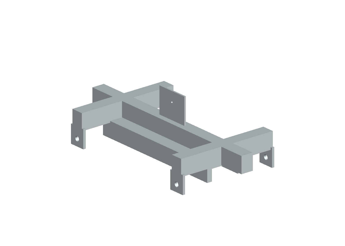
One below-the-hook lifting device carrying two vehicle interfaces. A bored eye plate on the vertical centreline takes the crane side. A longitudinal spine carries two lateral cross beams, and the four beam ends carry bored lift lugs in a rectangular pattern about the vehicle's centre of gravity. Underneath, a cradle plate and two rails form a channel that engages the UUV carrier.
SHUBA-ADAPTER-001, built headless in NX 2606. One solid, 18 features, 5 bores, 2400 x 1200 x 710 mm.
It is driven by 22 named expressions, so every placeholder can be replaced with a real value and the part rebuilt from the script rather than re-modelled. Three interface checks run before any geometry is created, and the build refuses rather than producing a part that looks finished and does not fit.
Four lift points rather than one, because a UAV's centre of gravity moves with payload and fuel, and a single hardpoint concentrates the whole load into one airframe fitting. Four spread it into existing structure and control attitude while the deck is moving.
The measurement that changed the design
The crane hook was pulled out of Teamcenter and opened in NX rather than assumed. Two things came back that no amount of reasoning would have produced.
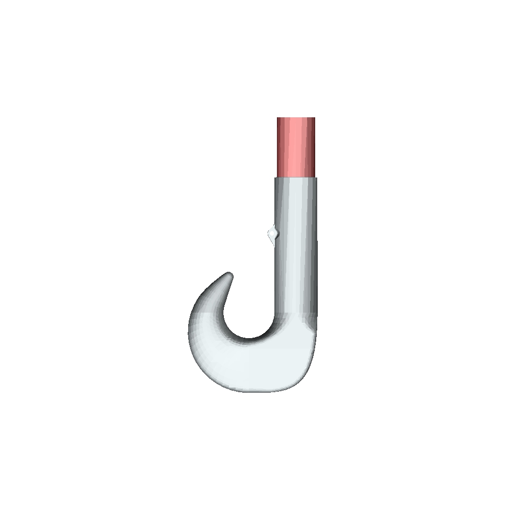
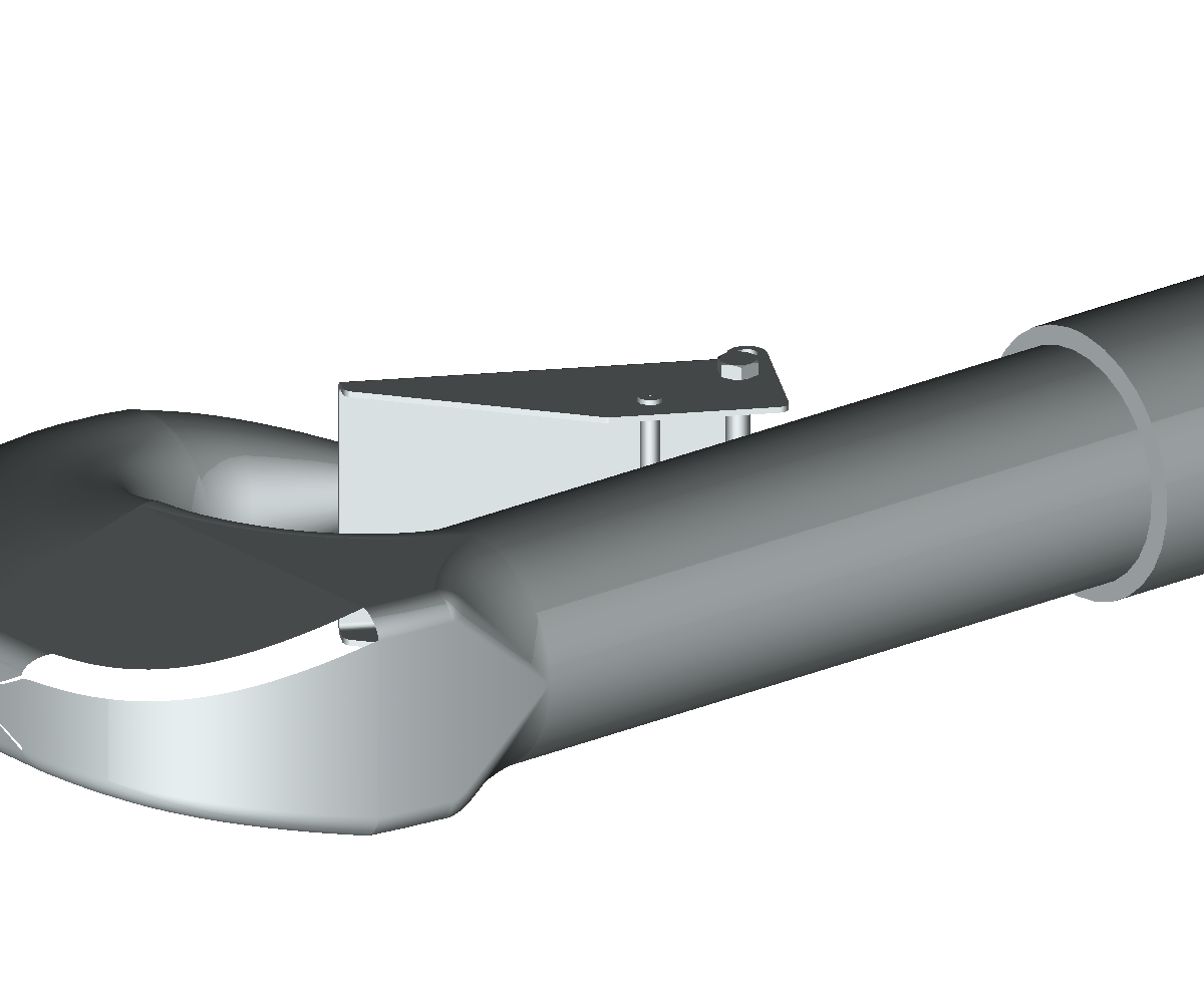
Item 033189, the crane winch cable hook, as it exists in the ship model. Left, the hook body alone in plan: 118 x 257 x 40 mm, and the opening the adapter had to clear. Right, the whole fitting with its shank and safety latch. The part is dimensioned in inches.
The ship model is in inches. The hook part reports its units as inches; the adapter, authored separately, is metric. The same call in the same session returns different answers for the two parts, so the reading discriminates rather than defaulting.
Nothing in that model should be assumed metric until its own part is checked. Later, importing the hook into a metric assembly with an explicit 25.4 scale produced a hook twenty-five times too big, because NX already converts on import. A control measurement caught it before it reached any result.
The second finding was dimensional. The hook's inner opening measures roughly 47 mm. The adapter's eye plate, as first drawn, was 40 mm thick. Seven millimetres is not a working fit once paint, tolerance and a moving deck are allowed for.
Thinning the plate would have been the wrong fix: it weakens the part to suit a fitting it was never meant to enter. Instead a shackle now goes between the hook and the adapter. The hook takes the round pin it was designed for, the adapter takes a clean pinned eye, and the shackle is a consumable that can be replaced without touching either.
That decision added two requirements, and the geometry was rebuilt from the script to suit: the eye plate went from 40 mm to 20 mm and its bore from 80 mm to 22 mm, sized to the shackle pin.
Checking it fits
The hook and the adapter were brought into one assembly and tested for interference at solid level.
As intended
0 of 7
hook bodies intersect the adapter
Control, driven 150 mm in
4 of 7
hook bodies intersect, same instrument
The control is the point. A clean result from a test that cannot fail is worth nothing, so the adapter was deliberately driven into the hook to confirm the check detects interference before the passing result was believed.
The thread, end to end
1
Read the ship
Item 031137 opened over the PLM service layer: structure, crane components, the UUV and its carrier. Nothing assumed, everything read back.
2
Write the interface
35 requirements authored as native objects and placed inside specification 034666 as numbered content, so exports, baselines and variant conditions can all see them.
3
Measure the hook
The hook's own part file retrieved from the vault and opened in NX. Units and opening measured. The design changed as a result.
4
Design the adapter
Built headless from a script whose driving expressions are the specification's parameters, with the interface checks enforced at build time.
5
Prove the fit
Static interference against the real hook geometry, with a positive control.
6
Put it back
The adapter checked in as part 034667 with its NX model as a managed dataset, and a trace link to the specification it was built against. The file was downloaded again and compared byte for byte to prove the content is really there.
How it was built
No interactive sessions. Teamcenter was driven over its JSON service layer, and NX ran headless, scripted through its open API. Every object named on this page came back from a call; none was transcribed from an intention.
The adapter is generated by a build script, so the model and its parameters cannot drift apart. Change a value, re-run, get the part.
The requirements were placed into the specification one at a time, because placing several in one call has been measured to write duplicates.
Every write was verified from a separate process with its own login. A re-read inside the writing session passes whether or not anything was committed.
The check that mattered most. When the adapter was first checked in, the upload returned success, the commit reported no errors, and the file appeared in the dataset's contents. All three passed on a dataset that had no content at all.
Only asking the vault for the file's size exposed it: the record pointed at a path that had never been written. The check-in was redone and then proved by downloading the file again and comparing its hash to the original.
The operation, in motion
Every frame is rendered from the real ship model. The crane's luff, the ram's stroke, the hook's plumb hang and the rope's length all come from one definition shared by the renderer and the clearance checks, so the animation cannot show a pose the checks have not passed.
Deployment. Pick at 10 degrees of luff, hoist off the cradle, swing aft with the winch stopped, lower past the transom, release at the waterline.Retrieval, which is not the deployment reversed. The vehicle comes to the crane, there is a hook-on dwell, and it is lifted clear of the water before anything luffs.
The crane could not do this as built. The transom is a flat plate at X 1344 and the stern rail reaches 0.7 inches further aft still, so the vehicle's nose has to clear both before it can descend. That needs 64 degrees of luff, and the ram's stroke caps it at about 30.
Moving the ram's lower pin 50 inches aft and 36 inches down onto a new bracket reaches 64 degrees on the same cylinder, using 32.3 of the 35 inches available. The cost is a peak pin load about 2.1 times the original, which is an open stress check, not a result.
The UAV interface
The vehicle is the QX-250: a 250 mm wheelbase quadcopter, 0.50 kg all up, four five-inch propellers. A 0.50 kg aircraft is not craned off a ship on a 1500 kg A-frame, so the adapter's UAV side is a capture nest rather than a sling: somewhere to hold the aircraft while the ship moves.
Arms into the troughs, body into the pocket, and the four retention posts landing in the gaps between the propeller discs. That is why the nest sits 45 degrees to the aircraft's flight axes.
The nest mounts on the after working deck at frame X 1178, 46 inches to port, on a pedestal clear of the roller rails, which occupy Z 142.6 to 147.1. There is no video of it in place: the nest is 10.2 inches across on a 127 foot ship, and the renderer will not draw an object that small inside a scene that large. Fitting the view tightly onto it returns a blank frame, and at a workable zoom it falls below the threshold entirely. The position is measured; the shot is not available.
Made ashore
Both new parts print. Neither video is a process simulation: they show material appearing in layer order and say nothing about scan strategy, thermal history, distortion, supports or build orientation.
SHUBA-UAV-NEST-001, 260 x 260 x 94 mm. One piece, no welds, inside any powder-bed volume. This is the part that genuinely earns additive.SHUBA-RAM-BRACKET-001's cheek and pin node, 1219 x 229 x 451 mm. The bracket as a whole is flat plate and wants flame-cutting and welding; only this node is worth printing, and only because the 2.1x pin load concentrates here.
Honest scope
What is real, what is provisional, and what has not been done.
Item
Status
Ship, crane and UUV geometry
real existing models, read not authored
Interface specification, 35 requirements
real native objects, placed as spec content
Hook units and envelope
measured from the hook's own part file
Adapter geometry
real model, checked in and trace linked
Adapter dimensions
placeholders every value tied to an open requirement
Hook inner opening, 47 mm
approximate scaled from a render, not a CAD measure
Shackle size
proposed follows a rated load that is still open
UAV vehicle
representative QX-250 chosen; wheelbase, props, arms and mass sourced, airframe geometry constructed
Stress and load analysis
not done
Interference against the full crane and ship
not done hook only
Manufacture ashore, work instruction
not done
Deployment and recovery videos
done rendered from the ship model, checks run before every frame
Ram bracket to reach the luff
real model, verified against the measured transom and rail
Ram bracket sizing
placeholders cheek and plate thickness; 2.1x pin load is an open stress check
UAV capture nest
real model, propeller clearance measured at 24.6 mm
Nest retention
not done no strap, latch or magnet designed
Additive build videos
geometric layer order only, not a process simulation
Nest shown in place on the ship
not done renderer will not draw a 10 in object in a 127 ft scene; position measured, shot unavailable
The adapter is a concept whose arrangement is a real design choice and whose numbers mostly are not. The model carries that warning as an attribute, so the caveat travels with the geometry rather than living only on this page.